Have you ever been in need for a precise PWM control on motors throughout an extended temperature range but your ultra low cost micro controller doesn’t support your toughest requirement? That’s a common issue quite easy to solve, just read through the article to find a good advice. We’ll use a design reference using ATmega328p because it is widely used and adopted in Arduino UNO boards.
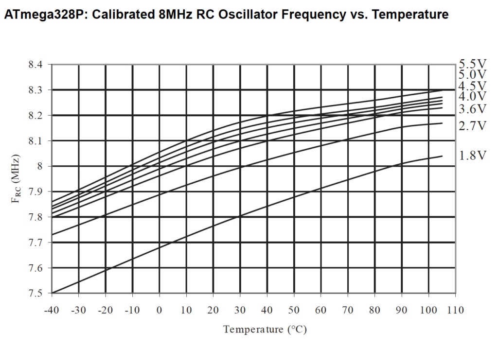
One of recurring issues using a micro-controller device is clock accuracy that feeds internal timer modules: on low-cost projects is often available a low frequency quartz oscillator to implement RTC functionalities without need for a costly external module. In this cases our micro controllers runs its internal core and peripherals using an internal RC oscillator with poor characteristics (in fabric calibration gives you 10 % accuracy) and very susceptible by temperature variations. Looking at constructor data sheet is evident how cannot use internal timers fed by a so poor clock reference.

In the following will be proposed a simple method to compensate problems using this internal RC oscillator by compensation from external reference at 32768 Hz. Those external low-cost quartz oscillator have superior properties for absolute value: temperature and aging drift are calculated into parts for million … no more percentages.
A typical application: precise PWM generation for motor controls, these PWM sort out from internal timer modules which, in low-cost projects, must use internal micro-controller RC oscillator.
How it works
The very simple concept: to use two free running counters fed by two different clock sources, the result from compare must be continuously set into OSCCAL register which allows to compensate RC oscillator frequency thus enabling up to 1 % precision into whole temperature range (this last point is very precious in many real applications).
We use as reference data sheet from ATmega328p because widely distributed into Arduino UNO boards, the document is available from producer at this link.
For sure timer TC2 is configured with external asynchronous source, that means it uses 32768 Hz quartz connected to pins TOSC1 and TOSC2, from firmware bit AS2 is set into ASSR register. Remember I suppose this precondition because you are developing a low-power application for low-cost (mass production ?) design.
Now just set a periodic interrupt to calculate ratio between one timer fed by internal 8 MHz RC oscillator (example TC1, a 16 bit timer) and TC2. Let’s assume the simplest case with 1 second overflow of timer2 using divisor 128 (interrupt frequency [Hz] = 32768 [Hz] / 128 / 256 = 1 [Hz]). Into following code snippet we configure also Timer1 as free-running counter with prescaler 256: as timer1 clock is theoretically 8 Mz we expect each second a count of 31250 (that is 8000000 / 256).
// Timer 2 configuration - 8bit clock 32768 Hz
TCCR2B |= (1 << CS22) | (1 << CS20);  // prescaler / 128
TIMSK2 |= (1 << TOIE);                // Overflow Interrupt Enable

// Timer 1 configuration - 16 bit clock 8 MHz
TCCR1B |= (1 << CS12) | (1 << CS10);
Must implement the following algorithm expressed as pseudo-code:
For each second:
- Save timer1 counter value
- Compute tick counts difference from previous execution (one second later)
- If difference > 300 (+1 %) decrease OSCCAL, otherwise if difference < -300 (-1 %) increase OSCCAL
Attenzione: L’operazione di incremento / decremento su OSCCAL deve agire solo sui 7 bit meno significativi, il bit più significativo CAL7 stabilisce il range di frequenza, passare da un range all’altro può essere fatto tenendo conto della discontinuità che ne deriva.

Safety related application
This way of proceed can be used also in safety related application but the compensation for OSCCAL register must be limited: for that kind of applications is already in place a mechanism into firmware to evaluate continuously coherence between two distinct clock sources, in that case simply we added a limited compensation into OSCCAL. Clock source independence is granted, that is the safety related requirement we shall satisfy.


